Custom Membrane Switch Design & Sourcing Guide for OEM Project Managers
Custom Membrane Switch Design & Sourcing Guide for OEM Project Managers
By the KeypadOne Engineering Team · DONGGUAN ZHONGJIA PRINTING CO., LTD., Dongguan, China · Last updated: October 2026
A membrane switch is usually the least expensive part of an assembly and the one most likely to delay a launch. This guide walks through what a membrane switch actually is, how the layers stack up, which material decisions drive cost and durability, and what to put on a drawing so your first quotation is accurate. It is written for the people who own the schedule: project managers, hardware engineers and sourcing leads bringing a custom interface into production.
Key Takeaways
- A membrane switch is a sealed, printed interface, typically 0.8–2.0 mm thick, assembled from flexible layers rather than discrete mechanical parts.
- Most of the final unit cost is decided before you ask for a quote: layer count, overlay material, circuit technology, backlighting and tooling are the five largest drivers.
- Silver ink is the industry-default circuit technology. Etched copper on polyimide is the better answer when the tail flexes repeatedly, current draw is high or vibration is severe.
- Industry reference values: metal domes are typically rated 1–5 million actuations, and flat non-tactile constructions are commonly quoted at 5–10 million because stress is spread across the contact area.
- In our experience the failures that reach the field are usually design decisions rather than manufacturing defects — the print-to-lamination window, tail bend radius and adhesive selection dominate.

What Is a Membrane Switch?
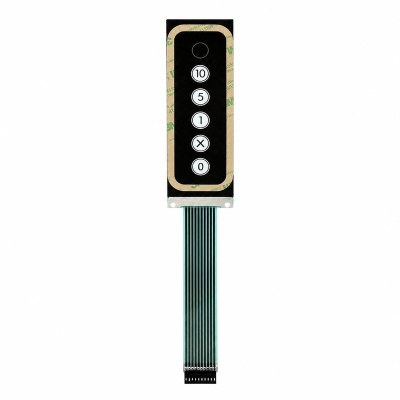
A membrane switch is a low-profile, sealed user interface assembled from printed flexible layers, typically 0.8–2.0 mm thick in a standard construction. It replaces discrete mechanical buttons in panels that must resist moisture, dust, cleaning agents and repeated actuation, which is why it appears far more often in medical devices, industrial control panels and appliances than in handheld consumer gadgets.
Unlike a mechanical keypad, a membrane switch has no moving parts above the panel surface. The actuation happens inside a sealed stack: pressing the overlay closes a small gap between two printed circuit layers and completes a circuit. That construction is what makes the assembly wipe-down safe, contamination-resistant and inexpensive to integrate into a front panel that also carries branding, indicator windows and legends.
For a project manager the practical implication is simple: the interface stops being a mechanical assembly problem and becomes a printed part. One supplier, one drawing and one inspection plan cover legends, seals, indicators and electrical contact together.
How a Membrane Switch Is Built: Layer by Layer
A standard membrane switch is a stack of six functional layers, and understanding the stack is the fastest way to understand where cost, durability and design risk come from.
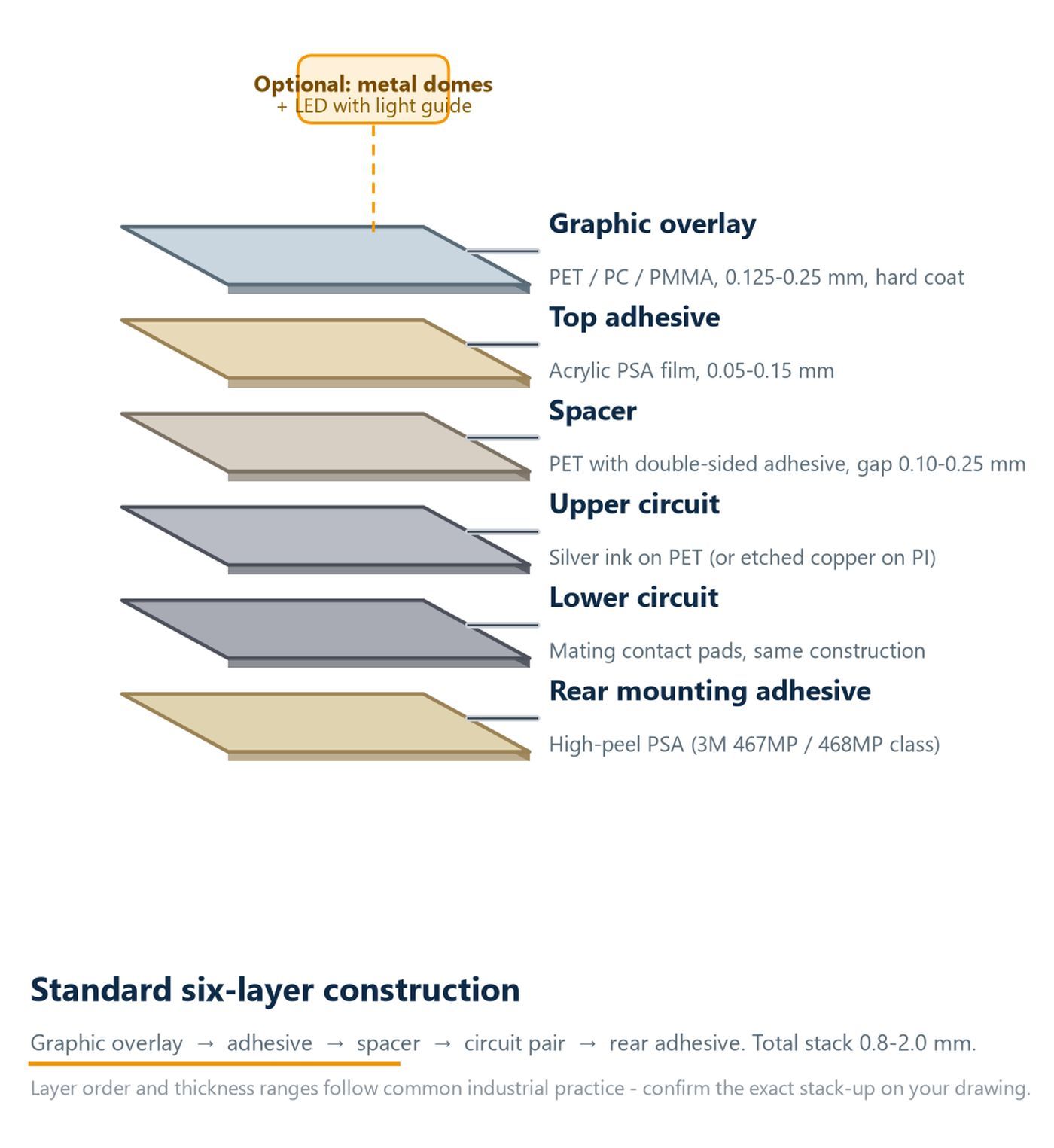
| Layer | Function | Typical material | What it decides |
|---|---|---|---|
| Graphic overlay | User interface, legends, branding, top protection | PET, polycarbonate or acrylic, commonly 0.125–0.25 mm with hard coat | Appearance, abrasion resistance, chemical resistance |
| Top adhesive | Bonds the overlay to the circuit stack | Acrylic or rubber-based adhesive film, 0.05–0.15 mm | Layering reliability, service temperature |
| Spacer | Holds the air gap between the two circuit layers | PET with adhesive on both sides, gap typically 0.10–0.25 mm | Actuation force and key feel |
| Upper circuit | Printed contact traces and pads | Silver ink on PET, or etched copper on polyimide | Conductivity, electrical lifespan |
| Lower circuit | Mating contact pads | Same construction as the upper circuit | Current capacity, contact stability |
| Rear mounting adhesive | Bonds the assembly to the enclosure | High-peel pressure-sensitive adhesive (3M 467MP / 468MP class) | Ingress protection, long-term adhesion |

Where design risk actually sits
Most assembly problems do not come from the printing. They come from the interfaces between layers.
Engineering note. Adhesion failures on returned panels rarely trace back to the adhesive grade itself. They usually come from surface energy on the overlay after printing, and from the delay between printing and lamination. That window shifts with ink coverage, ink type and ambient conditions, which is why we control it per material batch rather than per product model. It is the kind of check that never appears on a drawing, yet it decides whether a panel still looks new after two years in the field.
The second most common source of trouble is the tail, the flexible ribbon that carries signals from the switch to the main board. Bends that are sharp, repeated during assembly, or placed too close to a rigid stiffener will fail long before the contact pads do.
Key Materials and How They Affect Performance
Overlay material and circuit technology are the two material choices that most often determine whether a panel meets its specification. Both are specified on the drawing, so both should be decided early.
| Material | Choose it when | Watch out for |
|---|---|---|
| Polyester (PET) | Most industrial, medical and appliance panels. Dimensionally stable, prints cleanly, good chemical resistance, lowest cost of the three. | Lower impact resistance than polycarbonate, and embossing depth is more limited. |
| Polycarbonate (PC) | Panels exposed to impact, rough handling or aggressive cleaning. The most forgiving material for embossed keys. | More sensitive to certain solvents, so ink and adhesive selection matter more. |
| Acrylic (PMMA) | Applications where optical clarity, depth and a premium surface finish matter most. | More brittle than PET or PC, generally the highest material cost. |

Rear adhesives deserve the same attention. Standard acrylic pressure-sensitive adhesives begin to lose peel strength outside roughly −40 °C to +85 °C, and chemical wicking at the overlay edge is a known entry path for cleaning fluids, so the adhesive family should be selected against the real cleaning agents and temperature window rather than chosen by default. Metal domes add a defined actuation force and an audible click; they also add thickness and constrain key spacing, so both requirements belong on the drawing from the start.
Silver Ink or Copper Foil? Choosing the Circuit Technology
This is the single most consequential material decision in most membrane switch projects, and it is often made by default rather than deliberately.
Silver ink is the default for a reason. It is screen-printed in the same process as the rest of the stack, the tooling is straightforward, and for a flat or gently curved tail it performs reliably for the life of the product. Copper flex — etched copper foil on polyimide — costs more, but it tolerates far more flexing and carries higher current.
| Parameter | Silver ink on PET | Etched copper on polyimide |
|---|---|---|
| Manufacturing process | Screen-printed, no etching chemistry | Laminated copper, chemically etched |
| Minimum trace width / spacing | About 0.2–0.3 mm with standard screens | About 0.1 mm, supports 0.5 mm pitch tails |
| Closed-loop resistance | Commonly below 100 Ω | Commonly below 10 Ω |
| Repeated tail flexing | Limited; design for a one-time install bend | Rated for tens of thousands of dynamic bend cycles |
| Soldered components (LED, IC) | Conductive-epoxy attachment only | Direct soldering, far stronger joint |
| Silver migration risk in humidity | Manageable with carbon overprint and spacing | Not applicable |
| Relative cost | Baseline (1.0×) | Roughly 2–3× |
Engineering note. A practical rule: if the tail will be folded more than once during assembly, or routed through a hinge, ask your supplier to quote copper foil as an alternative before you freeze the design. Making that comparison at the drawing stage costs a few days; making it after tooling is cut costs a redesign. On one industrial controller project, simply widening the two longest tail traces from 0.5 mm to 1.0 mm removed an intermittent-contact complaint that had survived three prototype rounds.
Membrane Switch vs. Capacitive Touch Panel vs. FPC: Which Should You Specify?
These three technologies are frequently compared as if they were competitors. They are not. A membrane switch is a complete interface, a capacitive touch panel is a sensing layer, and an FPC is an interconnect. The useful question is which combination your product needs.
| Membrane switch | Capacitive touch panel | FPC (flexible printed circuit) | |
|---|---|---|---|
| What it is | A complete, sealed front-panel interface bonded behind the overlay | A sensing layer, usually bonded behind glass — not an interface on its own | A flexible interconnect between the interface and the main board |
| Actuation | Physical press, optional tactile dome | Light touch, generally no tactile feedback | Not applicable |
| Sealing | Excellent; the whole stack is sealed | Depends on glass bonding and enclosure design | Not applicable |
| Best when | Buttons must be discrete, glove-friendly, sealed, cleanable and cost-efficient | Gestures, dynamic UI or a glass front surface is required | You need to connect the interface to the main board, sometimes through a hinge |
| Avoid when | You need multi-touch or a dynamic display area | Operators wear thick gloves or need tactile confirmation of every press | You are treating it as a substitute for a switch |
In practice, most industrial and medical products use a membrane switch for fixed functions and reserve a capacitive panel for the parts of the user interface that genuinely change. Many designs we build combine both, plus an FPC tail, in the same front-panel assembly.
What Drives the Cost of a Custom Membrane Switch?
Unit price is a consequence of the drawing, not of the supplier’s generosity. These are the variables that move cost, roughly in order of impact.
| Cost driver | Why it matters | How to control it |
|---|---|---|
| Layer count | Every additional layer adds material, lamination steps and inspection points. | Combine functions into one layer where the design permits; avoid decorative layers that could be printed. |
| Overlay material | PET, PC and acrylic differ substantially in material cost and processing difficulty. | Specify PC or acrylic only where impact resistance or optical clarity genuinely require it. |
| Circuit technology | Copper foil costs more than silver ink in both material and lamination complexity. | Use silver ink unless repeated flexing, current or vibration demands copper. |
| Tooling | Screens and dies are one-time costs; complexity and tolerance class drive them. | Lock the layout before tooling. Revisions after cut screens are the most expensive kind. |
| Order quantity | Tooling and setup amortise across the run. | Share a realistic annual forecast, not a single order quantity. |
| Backlighting | LEDs, light guides and additional assembly steps add material and labour. | Use backlighting only on functions that must be visible in the dark. |
| Shielding and special adhesive | EMI shielding and application-specific adhesives add cost and lead time. | Specify only where the electrical or environmental requirement is confirmed. |
| Testing requirements | Higher inspection levels increase unit cost. | Agree an inspection plan proportionate to the product risk and end market. |

As a market reference point, published 2026 industry estimates place consumer-grade parts at roughly US$2–8 per unit in the 1,000–10,000 piece range plus US$500–3,000 of tooling, and industrial or medical grade parts at roughly US$8–30 per unit plus US$2,000–5,000 of tooling. Treat those numbers as orientation only: the drawing, not the category, sets the price.
When you compare quotations from several suppliers, compare them against the same column of this table. A lower quote that quietly uses a thinner overlay, omits a shielding layer or reduces the inspection plan is not a cheaper part; it is a different part.
MOQ, Tooling and Lead Time: What OEMs Should Expect
There is no universal MOQ or lead time for membrane switches, because both are functions of tooling, material and inspection plan rather than of the product category. Treat any supplier who quotes a single fixed number without asking about your drawing as a warning sign.
What determines the real answer:
- MOQ is driven by the tooling built for your part and by the minimum purchase quantity of the specific overlay material, adhesive and backlight components involved.
- Tooling cost is a one-time charge covering screens and dies. It is quoted separately from unit price and is the main reason small first orders carry a higher effective unit cost.
- Lead time splits into two very different phases: prototype and first-article, and mass production. Prototype lead time is dominated by engineering review and material availability; mass production lead time is dominated by capacity scheduling and inspection.

| Stage | Typical quantity | Industry-typical lead time | What actually sets the clock |
|---|---|---|---|
| Engineering review / DFM feedback | — | 1–3 working days | Completeness of the drawing |
| Prototype and first article | 1–20 pcs | About 2–3 weeks | Material availability and approval loops |
| Pilot batch | 50–500 pcs | 3–4 weeks | Tooling completion and yield ramp |
| Mass production | 1,000+ pcs | 4–6 weeks | Capacity scheduling and inspection plan |
These ranges reflect common industry practice, not a commitment: confirm both phases in writing against your actual drawing. A supplier who confirms tooling cost, MOQ and both lead-time phases against your drawing is telling you they have read it.
12-Point DFM Checklist Before You Send a Drawing
Most quotation delays and post-tooling changes trace back to information that was missing from the drawing. Run this list before you send it.
- Overlay material and thickness are named explicitly, not described as “standard”.
- Surface finish is specified: gloss, matte or textured, plus whether a hard coat is required.
- Legend colours are referenced to a standard (Pantone, RAL) and translucency is stated for backlit areas.
- Tolerance class is defined, particularly for window and cut-out dimensions that interface with the enclosure. ±0.15 mm on critical cut-outs is a common precision target; tighter than that raises cost quickly.
- Key spacing and actuator layout are dimensioned, with the actuation force target if tactile feedback is required.
- Metal dome positions and orientation are marked if domes are used, including venting provision.
- Circuit technology is stated: silver ink or copper foil, with the reason if copper is required.
- Tail exit position, length and bend route are dimensioned, including any fold that will happen during assembly. Keep the bend radius at least about six times the tail thickness and never fold directly at a stiffener.
- Connector type and pinout are specified, or the termination method is stated if the tail is soldered directly.
- Backlighting requirements are defined: illumination areas, LED colour, and whether a light guide is needed.
- Adhesive and sealing requirements are noted, including the cleaning agents the panel must withstand.
- Inspection and packaging requirements are agreed, including whether 100% functional test is required.
A drawing that answers all twelve points typically moves to tooling without a second round of questions. One that answers eight usually comes back twice. If you would like a second pair of eyes first, you can send your drawing for an engineering review before quoting — the useful output is a list of design risks, not a price.
Designing for Durability: Life Cycles, Sealing and Environment
Durability in a membrane switch is mostly decided by four things: the actuation mechanism, the sealing strategy, the operating environment and the tail. Get those right and the panel will outlast the product it is fitted to.
| Construction | Typical actuation life (industry reference) | Notes |
|---|---|---|
| Metal dome, tactile | 1–5 million actuations | Defined force and audible click; stress concentrates at the dome |
| Poly dome, tactile | 100,000–300,000 actuations | Lower cost, softer feel |
| Non-tactile, flat polyester | Commonly quoted at 5–10 million actuations | No moving dome; stress distributed across the contact area |
These ratings assume operation within the specified force range. Exceeding the rated actuation force by 50% can reduce cycle life by 60–80%, so a target force should be set with your supplier rather than assumed. Standard PET-based constructions operate reliably from about −40 °C to +85 °C; polyimide circuit substrates with high-temperature adhesives extend that window.
On sealing, a membrane switch is inherently well sealed because the whole stack is laminated. Where panels fail in the field it is usually at the edges and around the tail exit, so the enclosure interface and the tail grommet deserve as much attention as the switch itself. For outdoor or wash-down use, ingress protection is normally expressed as an IP rating per IEC 60529: IP65 for dust-tight and jet-water resistance, IP67 for temporary immersion, with the rating verified by test rather than self-declaration.
Engineering note. Confirm the real operating window, including wash-down chemicals, cleaning agents, UV exposure and condensation. Autoclave or aggressive solvent exposure should be stated explicitly, because it changes material selection: polycarbonate overlays can stress-crack in contact with alcohols and ketones, while hard-coated PET handles quaternary ammonium disinfectants far better.
Certifications and Compliance for Global Markets
For most projects the certifications that matter divide into two groups: the quality management systems your customer’s procurement team will audit, and the material compliance evidence your customer’s regulatory team will file.
DONGGUAN ZHONGJIA PRINTING CO., LTD. (KeypadOne) operates under ISO 9001:2015, ISO 14001:2015, ISO 45001:2018 and ISO 14064:2018, together with IATF 16949:2016 for automotive work and QC 080000:2017 for hazardous substance process management. The company is recognised as a National High-Tech Enterprise and a Guangdong “Specialized, Refined, Distinctive & Innovative” SME. On the product side, materials comply with RoHS Directive 2011/65/EU as amended, and with REACH Regulation (EC) No 1907/2006 obligations for substances of very high concern; SGS test reports are available, and UL certification applies to selected products.

Two cautions are worth carrying into any supplier conversation. First, UL coverage is normally limited to selected products and constructions, so ask for the specific file reference that covers your part rather than a general claim. Second, IATF 16949 changes the working relationship more than the certificate implies: it brings defined change control, traceability and production-part approval expectations that should be agreed at the start of the programme, not at the first audit.
Quality Control and Traceability: How We Test
Inspection should be designed around the failure modes the design can actually produce. These are the checks used on production at KeypadOne, and what each one catches.

| Test / control | Equipment | What it catches |
|---|---|---|
| Visual and barcode inspection | CCD vision inspection system with barcode verification | Print defects, missing legends, misregistration, traceability errors |
| Material compliance | RoHS / halogen analyser | Restricted substances and halogen content outside specification |
| Adhesion | Adhesion tester | Weak bonds between the overlay and the circuit stack |
| Environmental durability | Thermal cycling chamber | Layering failures and material stress under temperature swings |
| Peel strength | Peel strength tester | Adhesive performance on tails and laminated interfaces |
| Electrical integrity | PCB short-circuit tester | Short circuits and continuity faults before assembly |
Testing only becomes useful when it is connected to a record. KeypadOne runs ERP and MES systems across production so that material batches, process parameters and inspection results stay linked to the specific parts shipped, supported by a quality organisation of around 90 QC staff and a 30-person R&D and engineering team. For a customer, the practical benefit is straightforward: when something needs to be investigated eighteen months later, the data still exists, and a containment decision can be scoped to an actual batch instead of a guess.
If you want that review applied to your own panel, you can contact the engineering team directly with your drawing and target specification.
Applications and Industry-Specific Requirements
The same construction serves very different markets, but the requirements that decide acceptance differ substantially. This is where a supplier’s experience shows up in the quotation.
| Industry | What governs acceptance |
|---|---|
| Home appliances | High volume, tight unit cost, cleaning-agent resistance, consistent legend appearance across large runs |
| Industrial equipment | Long service life, EMI considerations, robustness against operator wear, glove-friendly actuation |
| Medical devices | Cleanability and disinfectant compatibility, documentation, change control, traceability |
| Automotive electronics | IATF 16949 discipline, change control, production-part approval, wide temperature range |
| Telecom and AI data-centre hardware | Precise legends, shielding, low profile, consistent appearance across rack-mounted units |
| Office equipment and 3C | Cosmetic quality, embossing and backlighting, cost sensitivity at volume |
How to Choose a Membrane Switch Manufacturer
Price is the easiest thing to compare and the least predictive of programme success. These are the questions that separate suppliers who can carry a project from those who can only quote one.
| Assessment area | What to ask |
|---|---|
| Engineering capability | Will they review and redline your drawing before quoting, and does that review come from an engineer? |
| In-house processes | Are printing, die-cutting, lamination and assembly controlled in-house, or outsourced? |
| Testing and inspection | What is tested on every order, with what equipment, and what data is retained? |
| Traceability | Can they link a shipped batch back to material lots and process parameters? |
| Certification fit | Which certifications actually apply to your part, and can they show the file reference? |
| Capacity and scheduling | What monthly capacity is committed to your product family, and how is it protected at peak? |
| Prototype responsiveness | How quickly do they turn a drawing into a functional sample, and how many rounds are included? |
| Communication | Is there a single engineering contact who answers technical questions directly? |
For a worked example of what that review looks like in practice, see our membrane switch dome design optimisation case study, where a shared three-key dome was redesigned into three independent domes before tooling.
Frequently Asked Questions
What is the minimum order quantity for a custom membrane switch?
There is no industry-wide MOQ. The real constraint is the tooling built for your part and the minimum purchase quantities of the specific overlay, adhesive and backlight materials involved. Give your supplier a realistic annual forecast rather than a single order quantity, and ask for MOQ to be quoted against your actual drawing.
How long does it take from drawing to production?
It divides into two phases with different constraints. Prototype and first-article time is driven by engineering review and material availability, commonly two to three weeks; mass production time is driven by capacity scheduling and the inspection plan, commonly four to six weeks. Ask for both phases separately and for the assumptions behind them.
What files do you need for a quotation?
A dimensioned drawing in DXF, DWG, PDF or AI format, or Gerber data for the circuit layer. It must state material, thickness, surface finish, tolerance class, tail exit position, connector type and order quantity. A photograph and a verbal description are not enough to quote accurately.
Can membrane switches survive humid or outdoor environments?
Yes in many cases, because the laminated stack is inherently well sealed. The limiting factors are the edge and the tail exit, plus sustained UV exposure on the overlay. Outdoor use is realistic with the right material and enclosure design; continuous direct sunlight is a separate question that should be raised explicitly at the drawing stage.
What is the difference between silver ink and copper foil circuits?
Silver ink is printed in the same process as the overlay, keeps tooling simple and is the default for most panels, with closed-loop resistance commonly below 100 Ω. Copper foil costs more but tolerates far more flexing and carries higher current, with resistance commonly below 10 Ω. Choose copper when the tail bends repeatedly during assembly, when current draw is high, or when vibration is severe.
How many press cycles can a membrane switch last?
It depends on the actuation mechanism, the force applied, the stroke and the environment rather than on a single published figure. Metal domes are typically rated 1–5 million actuations; flat non-tactile constructions are commonly quoted at 5–10 million because stress is distributed across the contact area. Set a target cycle count with your supplier based on your real usage pattern.
Are your membrane switches RoHS and REACH compliant?
Yes. Materials comply with RoHS Directive 2011/65/EU as amended and with REACH Regulation (EC) No 1907/2006 obligations, and QC 080000:2017 hazardous substance process management is in place, supported by SGS test reports. UL certification applies to selected products, so request the file reference that covers your specific construction rather than a general statement.
Can you integrate LED backlighting and metal domes in one assembly?
Yes, and it is a common combination on industrial and medical panels. Both add thickness: domes provide tactile feedback, and LED backlighting with a light guide illuminates selected areas. The layout constraints involve dome spacing and light-guide routing, so introduce both requirements at the drawing stage.
Do you support IATF 16949 automotive projects?
KeypadOne operates under IATF 16949:2016. For automotive programmes this means defined change control, traceability and production-part approval expectations are agreed at the start rather than discovered at audit. Automotive work also typically requires a wider qualified temperature range and documented process capability, both of which should be specified with the drawing.
How do you handle design changes after tooling?
Changes are handled through a documented revision process: the drawing is versioned, the impact on tooling and lead time is quoted before work starts, and the change is recorded against the affected batch. The cost of a change is proportionate to how late it arrives, which is the strongest argument for running the DFM checklist before screens and dies are cut.
Next Step: Request a Quote or Upload Your Drawing
If you are specifying a custom membrane switch, the fastest way to get an accurate answer is to send the drawing. Our engineering team reviews it, flags any design risks before quoting, and comes back with tooling cost, MOQ and lead time for both prototype and production phases. You can request a quotation or upload your drawing here.
What to include with your enquiry:
- Dimensioned drawing (DXF, DWG, PDF, AI or Gerber)
- Overlay material and thickness, plus surface finish and hard-coat requirement
- Circuit technology preference, or the flexing and current conditions if undecided
- Tail exit position, length, bend route and connector or termination type
- Backlighting and tactile feedback requirements, if any
- Annual forecast and first-order quantity
- Target market and any compliance requirements (RoHS, REACH, UL, IATF 16949)
About the Manufacturer
Founded in 2009, with roots in the industry going back to 2006, KeypadOne is the membrane switch and user-interface brand of DONGGUAN ZHONGJIA PRINTING CO., LTD., a vertically integrated precision printing manufacturer in Dongguan, Guangdong. The company operates a 20,000 m² facility with dust-free workshops and automated lines, staffed by approximately 400–450 people including around 30 R&D engineers and 90 QC specialists. Monthly capacity covers approximately 10 million nameplates, 1 million membrane switches, 50 million labels and 30 million die-cut parts. Product lines include electronic nameplates, membrane switches, touch panels, flexible printed circuits (FPC), self-adhesive labels, die-cut parts, industrial tapes and structural parts, serving home appliances, office equipment, consumer electronics, medical devices, industrial equipment, telecom and AI data-centre hardware, and automotive electronics. Address: No.1 Shunxing Street, Liangjia Village, Shijie Town, Dongguan City, Guangdong Province, P.R. China.