
For Project Managers

Keep your program on schedule — no hidden risks, no late-stage surprises, no delivery setbacks.
Home / For Project Managers

KeypadOne:Securing Your NPI Timeline from EVT to Stable Mass Production

  • DFM risk review at design freeze — before tooling spend
  • Gate-by-gate milestone tracking from EVT through PVT
  • Yield-stable handover from PVT to mass production
We know the hardware PM’s biggest headache: late-stage ECOs that wreck your budget and reset your NPI clock. At KeypadOne, we don’t just manufacture—we proactively de-risk. By auditing your Gerber files and mechanical stack-ups during EVT/DVT, we catch material incompatibilities, electrical layout constraints, and assembly tolerances before they hit the PVT line. Our actionable, gate-ready DFM feedback prevents costly re-spins, secures your timeline, and guarantees a predictable, high-yield transition to stable Mass Production (MP).Send your drawings for a DFM review

4 Risks That Derail a Hardware Program — and How We Close Them

Potential Risks 01

Uncontrolled Delivery Cycle & Milestone Slippage

Verbal agreements lack milestone-based governance. Prototyping and mass production schedules are subject to fluctuations in factory capacity priority, resulting in frequent project plan changes and reactive stakeholder reporting.

Solution 01

Milestone-Gated Project Management System

5-stage gated delivery mechanism: Requirements Freeze → DFM Review & Quotation → Prototyping → Sample Validation & Approval → Volume Production Ramp-up. Fixed timeline per gate; production scheduling is initiated immediately upon sample approval.

Potential Risks 02

Multi-Vendor Fragmented Sourcing & Excessive Coordination Overhead

Sourcing membrane switches, graphic overlays and FPCs from separate suppliers easily leads to dimensional interface mismatch and blurred accountability. Each design iteration requires full-chain re-coordination.

Solution 02

Single Engineering Interface Across Full Product Lines

In-house R&D and manufacturing for membrane switches, graphic overlays, touch displays and FPCs. A unified engineering team oversees structural matching and process consistency; interface alignment issues are closed-loop internally.

Potential Risks 03

Iterative Prototyping Revisions & EVT Phase Schedule Overrun

Design issues exceeding process limits are only exposed after prototyping. Each design re-spin takes a minimum of 3–5 days, causing overall delay to the engineering validation plan.

Solution 03

Complimentary Pre-Prototyping DFM Manufacturability Review

Full-dimensional audit prior to tooling: trace width, hole position, die-cut geometry, layer stackup, tolerance chain, assembly interference. Process risks are intercepted before design freeze.

Potential Risks 04

Stable Low-Volume Quality & Volume Production Yield Degradation

Quality is controllable in low-volume manual production, but yield drops and material variability occur after scale-up. Customer complaints and rework costs are passed back to the project.

Solution 04

First Article Inspection + Reliability Qualification + Dedicated QC Governance

First article inspection for critical dimensions, covering reliability qualification items such as actuation life, peel strength and thermal cycling. Volume production adheres to the same quality control standards as low-volume runs.

Materials and Layered Structures We Use

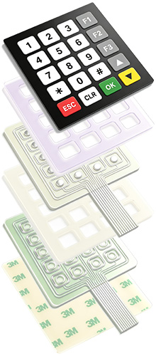
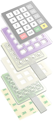
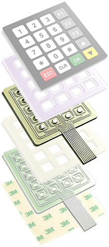
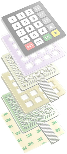
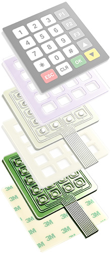
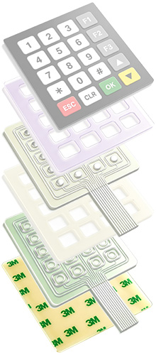
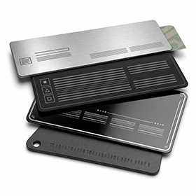
A membrane switch is a composite of 5–7 functional material layers. The material selected for each layer directly affects key feel, service life, and environmental adaptability. The following is a common stack-up that can be adjusted to your actual operating conditions.
  • 01

    Panel Layer

    Serving as the outer operating interface of the membrane switch, this layer uses a PET/PC film substrate with printed button markings, providing both aesthetic appeal and operational guidance, as well as dust and scratch resistance.

  • 02

    Adhesive Layer

    Used to bond the panel layer to the upper circuit layer, while also forming an interlayer seal barrier to effectively prevent moisture and dust from entering the internal circuit area.

  • 03

    Upper Circuit Layer

    Conductive circuits and contacts are printed on a PET insulating film substrate. When the button is pressed, the contacts deform and adhere downwards with the substrate, triggering circuit conduction.

  • 04

    Giver Layer

    Serving as a flexible isolation structure between the upper and lower circuit layers, this layer normally separates the contacts to prevent accidental triggering, and provides deformation space and assists in circuit reset when pressed.

  • 05

    Lower Circuit Layer

    Corresponding to the upper circuit layer, this layer forms a complete control loop, integrating signal lead-out cables to transmit button commands to the terminal device control module when conduction is achieved.

  • 06

    Adhesive Backing Layer

    This is the bottom mounting and fixing structure for the product. Industrial-grade double-sided adhesive is used to firmly attach the switch to the equipment mounting position, and it also serves as a bottom seal.

DFM Engineering Support

Our engineering team reviews drawings for manufacturability risks before prototyping.

Quality & Compliance


- FMEA-driven quality system with strict CPK control for critical processes
- Proven reliability across temperature, humidity, vibration, and ESD environments
- Fully certified to IATF 16949, ISO 9001, UL, RoHS, and REACH standards
- Proactive IP and conflict minerals risk mitigation for seamless market entry


Technical Collaboration and Long-Term Support


- Early-stage DFM support to reduce design iterations and speed up R&D
- Formal closed-loop issue resolution with defined response protocols
- Lifelong capacity and technical support for spare parts and product evolution

Reliable Delivery


- End-to-end supply chain visibility with milestone-based timeline management
- Redundant contingency plans to offset raw material, capacity, and logistics risks
- Predictable lead times and consistent on-time order fulfillment

Transparent Cost Management


- Fully itemized quotations with clearly delineated cost categories
- Tiered pricing for prototype through mass production volumes
- Enables total cost optimization across the full procurement lifecycle

Four Core Products We Manufacture

The four product lines can be supplied independently or combined into a complete HMI module, with one engineering team coordinating structural and process consistency.

Membrane Switch

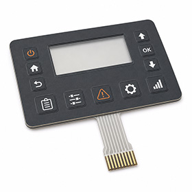
A key control interface formed by overlay, circuit layers, spacer, and adhesive. Metal domes can be added for tactile snap, with optional light-transmission windows and backlighting.

Flexible Printed Circuit

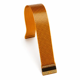
Conductive circuits carried on a flexible substrate, with bendable routing for compact assemblies. Often combined with membrane switches and touch panels as an integrated HMI module.

Electronic Nameplate

Precision-printed nameplates for equipment branding, ratings, and enclosure panels, with brushed metal, matte, gloss, and other surface effects plus customized adhesive options.

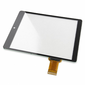
Touch Panel

A touch interface panel for display equipment, with customized outline dimensions, screen-printed borders, and tail positions based on the assembly structure, co-designed with the display module.

Five-Step Delivery Process

Standardized milestones make project progress predictable. Once samples are approved, production scheduling can begin directly.
Step 01

Requirements & Drawing Confirmation

Step 02

DFM Review & Quotation

Step 03

Sample Production

Step 04

Sample Approval

Step 05

Volume Delivery

Send us your drawings — we'll return a DFM report

Whether you're developing a new project or looking to replace an existing supplier, you can start with a free DFM review.