For Design Engineers

Precision-Printed Interfaces That Move Your Design from Sketch to Mass Production.
Home / For Design Engineers

Precision Interfaces Turning Your Design Vision into Reality

  • HMI Design
  • High-Density Flexible Interconnect
  • Collaborative R&D & DFM
  • Touch & Display Integration
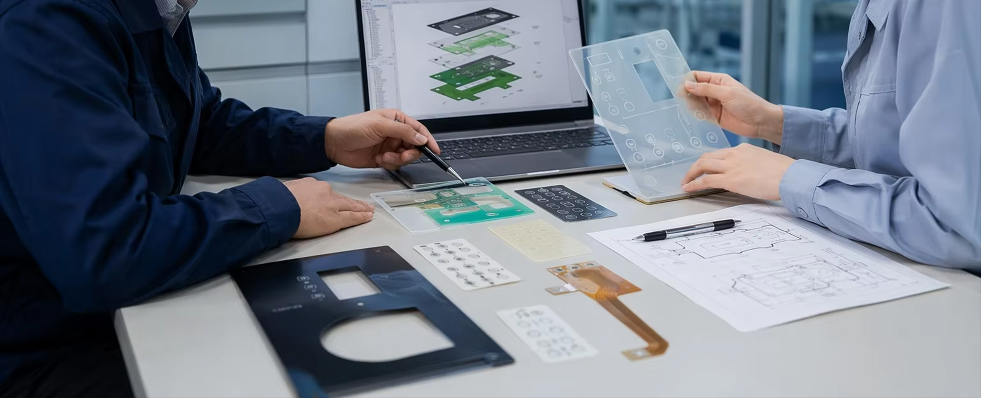
KeypadOne collaborates with engineering teams to review drawings and identify potential production risks early on. We provide actionable feedback on Design for Manufacturability (DFM), material compatibility, surface treatments, circuit layout, bonding structures, and production consistency, helping your designs transition more smoothly from the engineering validation phase to stable mass production.Submit your design drawings for DFM review

Beyond Manufacturing

Become an engineering partner that understands and implements design
Potential Risks 01

Manufacturability Verification

CAD designs often ignore process limits—fine lines, micro-spacing, complex stack-ups push beyond mass-production capability, leading to frequent re-spins in prototyping.

Solution 01

DFM Review

Comprehensive DFM process review verifies linewidth, hole position, die-cutting, and stacking, anchoring process limits to ensure mass production feasibility.

Potential Risks 02

Cross-Domain Collaboration Verification

Disconnected multi-module designs mean that even minor changes can cause cross-domain interference in structural circuit assembly, resulting in high coordination costs.

Solution 02

Stacking and Interface Review

Joint review by multiple professional engineers verifies the baseline interface cross-sectional structure, proactively mitigating cross-system interference risks.

Potential Risks 03

Material Reliability Verification

Material selection relies on experience. Under complex operating conditions, bonding failures and performance degradation are prone to occur, leading to late-stage risks.

Solution 03

Material Application Guidelines

Combining full-condition matching of substrates and adhesive systems, clarifying performance thresholds, and locking in full-cycle reliability boundaries.

Potential Risks 04

Tolerance Assembly Verification

Even if individual parts meet dimensional standards, accumulated tolerances can easily cause hole misalignment, touch abnormalities, and FPC stress assembly failure.

Solution 04

Critical Dimension Control

Proactively identifying critical dimensions and tolerance chains, coupled with first-article measurement and assembly verification, ensuring stable batch yield.

Materials and Layered Structures We Use

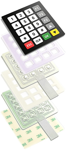
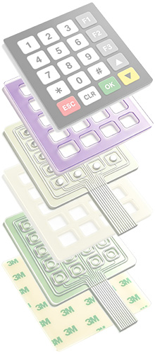
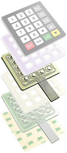
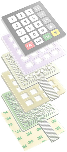
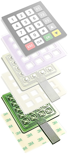
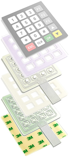
A membrane switch is a composite of 5–7 functional material layers. The material selected for each layer directly affects key feel, service life, and environmental adaptability. The following is a common stack-up that can be adjusted to your actual operating conditions.
  • 01

    Panel Layer

    Serving as the outer operating interface of the membrane switch, this layer uses a PET/PC film substrate with printed button markings, providing both aesthetic appeal and operational guidance, as well as dust and scratch resistance.

  • 02

    Adhesive Layer

    Used to bond the panel layer to the upper circuit layer, while also forming an interlayer seal barrier to effectively prevent moisture and dust from entering the internal circuit area.

  • 03

    Upper Circuit Layer

    Conductive circuits and contacts are printed on a PET insulating film substrate. When the button is pressed, the contacts deform and adhere downwards with the substrate, triggering circuit conduction.

  • 04

    Giver Layer

    Serving as a flexible isolation structure between the upper and lower circuit layers, this layer normally separates the contacts to prevent accidental triggering, and provides deformation space and assists in circuit reset when pressed.

  • 05

    Lower Circuit Layer

    Corresponding to the upper circuit layer, this layer forms a complete control loop, integrating signal lead-out cables to transmit button commands to the terminal device control module when conduction is achieved.

  • 06

    Adhesive Backing Layer

    This is the bottom mounting and fixing structure for the product. Industrial-grade double-sided adhesive is used to firmly attach the switch to the equipment mounting position, and it also serves as a bottom seal.

DFM Engineering Support

Our engineering team reviews drawings for manufacturability risks before prototyping.

Process Feasibility & Assembly DFM

Pre-prototype review of stack-up, critical holes/windows, tail routing, connector clearance, bonding areas, and assembly interference.

DFM Outputs: structural adjustments, process route review, assembly risk checklist.

Reliability Testing DFM

Matching product structure to actual application conditions—temperature, humidity, cleaning agents, repeated pressing, bending, and long-term adhesion.

DFM outputs: recommended tests—peel strength, thermal cycling, keypad life, short-circuit detection, and adhesive aging verification.

Cost Feasibility DFM

Assessment of manufacturability via existing printing, die-cutting, lamination, and punching processes.

DFM outputs: material alternatives, panel nesting proposals, process simplification, and cost-reduction recommendations without compromising key functions.

Tolerancing Feasibility

Evaluation of critical dimensions for print registration, die-cutting accuracy, lamination alignment, connector positioning, and final assembly fit.

DFM outputs: practical tolerance ranges, review of quality-critical dimensions, and risk alerts for areas impacting yield or assembly.

Four Core Products We Manufacture

The four product lines can be supplied independently or combined into a complete HMI module, with one engineering team coordinating structural and process consistency.

Membrane Switch

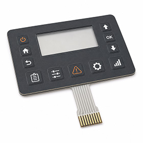
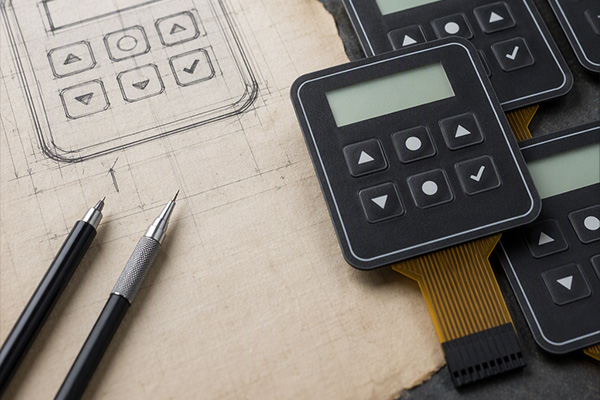
A key control interface formed by overlay, circuit layers, spacer, and adhesive. Metal domes can be added for tactile snap, with optional light-transmission windows and backlighting.

Flexible Printed Circuit

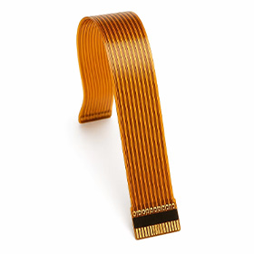
Conductive circuits carried on a flexible substrate, with bendable routing for compact assemblies. Often combined with membrane switches and touch panels as an integrated HMI module.

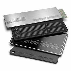
Electronic Nameplate

Precision-printed nameplates for equipment branding, ratings, and enclosure panels, with brushed metal, matte, gloss, and other surface effects plus customized adhesive options.

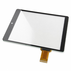
Touch Panel

A touch interface panel for display equipment, with customized outline dimensions, screen-printed borders, and tail positions based on the assembly structure, co-designed with the display module.

Five-Step Delivery Process

Standardized milestones make project progress predictable. Once samples are approved, production scheduling can begin directly.
Step 01

Requirements & Drawing Confirmation

Step 02

DFM Review & Quotation

Step 03

Sample Production

Step 04

Sample Approval

Step 05

Volume Delivery

Submit Your Drawings & Receive Engineering Feedback within 24 Hours

Whether you are developing a new project or replacing an existing supplier, we can start with a complimentary DFM review